The diode is one of the most important and simplest components in electronics.
One of the first things we learn about it is:
A diode allows current to flow primarily in one direction and blocks it in the opposite direction.
This characteristic becomes particularly interesting when we place a diode in a circuit powered by alternating current (AC).
That’s because the polarity of an alternating voltage changes continuously.
So a question arises:
If alternating current constantly changes direction and the diode conducts primarily in only one direction, what happens to the waveform after it passes through the diode?
That’s what we’re going to understand.
How Does a Diode Work?
A semiconductor diode has two terminals:
Anode (A) and cathode (K).
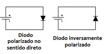
When the diode is subjected to the appropriate polarity for conduction, we say it is:
Forward-biased.
When the polarity is reversed, we say it is:
Reverse-biased.
As an initial explanation, we can think of it this way:
Forward bias → diode conducts
Reverse bias → diode blocks.
In practice, a real diode is not a perfect switch. It has characteristics such as forward voltage drop, reverse leakage current, and maximum voltage and current ratings.
But this simplified model is excellent for beginning to understand how it works.
What Happens with Direct Current?
First, imagine a battery powering a resistor through a diode.
If we place the diode in the correct orientation:
Power source → diode → resistor
It will be forward-biased and can conduct current.
If we reverse the diode:
Power source → reversed diode → resistor
It will be reverse-biased and, under normal operating conditions, will practically prevent current from flowing.
So far, it’s relatively simple.
But what happens when the voltage constantly changes polarity?
What Is Alternating Current?
In alternating current, or AC, the voltage varies over time and periodically reverses polarity.
A waveform commonly used to represent alternating voltage is the:
Sine wave.
It has two regions that we can call the:
Positive half-cycle
and
Negative half-cycle.
The process then repeats continuously.
In a 60 Hz electrical power system, for example, there are 60 complete cycles per second.
In a 50 Hz electrical power system, there are 50 complete cycles per second.
What Does the Diode Do to This Sine Wave?
Now things get interesting.
Imagine placing a diode in series with a load powered by a sinusoidal voltage.
During one of the half-cycles, the diode becomes:
Forward-biased.
During this period, it conducts.
When the voltage polarity reverses, the diode becomes:
Reverse-biased.
During this period, it blocks current, disregarding the small leakage currents of a real component.
The result is:
One half-cycle appears across the load, while the other is blocked.
This process is called:
Half-Wave Rectification
Does a Diode Convert Alternating Current into Direct Current?
This question deserves careful consideration.
After the diode, the voltage across a resistive load no longer alternates between positive and negative values in the same way as the original sine wave.
We have pulses that always have the same polarity.
But this is still not the nearly constant DC voltage we would expect, for example, from a battery.
What we have at the output of a half-wave rectifier is:
Pulsating DC voltage.
We can represent it as:
Sinusoidal AC
→ diode
→ half-wave rectification
→ pulsating DC.
To obtain a smoother voltage, we usually need to add other stages.
Why Is It Called “Half-Wave”?
Because we use only one of the two half-cycles of the sine wave.
Imagine:
Positive → passes through
Negative → blocked
Positive → passes through
Negative → blocked
And so on.
If we reverse the orientation of the diode, we can change which half-cycle appears across the load.
Therefore, it is not necessarily the positive half-cycle that must pass through.
This depends on the:
Orientation of the diode in the circuit.
There Is a Voltage Drop Across the Diode
So far, we have treated the diode almost like an ideal switch.
A real diode has a voltage drop when it conducts.
For a conventional silicon diode, a value close to:
0.7 V
is commonly used as a reference for educational purposes.
But this value is not an absolute constant.
The forward voltage depends on the component, the current, and the temperature.
Therefore, if the input voltage is low, this drop can be quite significant.
A Simple Example
Imagine a sine wave with a peak voltage of:
10 V.
With an ideal diode, we could expect approximately 10 V peak across the load during the conducting half-cycle.
With a real silicon diode, the peak will be slightly lower because of the forward voltage drop.
Approximately:
Vp(output) ≈ Vp(input) − Vf(diode)
If we assume approximately 0.7 V:
10 − 0.7 ≈ 9.3 V.
This is an approximation, but it helps us understand that a real diode also causes a small voltage loss during conduction.
So Does the Voltage Drop by Half?
Not exactly.
This is an important correction to the way I explained it in the original article.
The text stated that, because only one half-cycle passes through the diode, “only half the voltage” could pass through.
What actually happens is:
One of the half-cycles is eliminated.
The peak value of the remaining half-cycle does not simply become half of the original peak.
What changes are quantities such as:
Average value;
Root mean square (RMS) value;
Power delivered to the load.
Therefore, simply saying that the diode produces “half the voltage” can lead to a misunderstanding.
What About the RMS Value?
Here we find a very interesting consequence.
For an ideal full sine wave with a peak voltage of Vp:
Vrms = Vp / √2
For an ideal half-wave rectified sine wave:
Vrms = Vp / 2
This means that the relationship between the RMS values is not necessarily what we might imagine by looking at only half of the sine wave diagram.
What Happens to the Power?
For a purely resistive load:
P = Vrms² / R
Now notice something interesting.
Full sine wave:
Vrms = Vp / √2
Therefore:
P = Vp² / 2R
For half-wave rectification:
Vrms = Vp / 2
Therefore:
P = Vp² / 4R
Thus, for an ideal purely resistive load, the average power with half-wave rectification is:
Half the power delivered by the full sine wave.
This is where the idea used in the original project with an incandescent lamp comes from.
But now we can explain the reason correctly.
It is not because:
“The voltage dropped by half.”
It is because we changed the waveform and, consequently, its RMS value.
The Incandescent Lamp Example
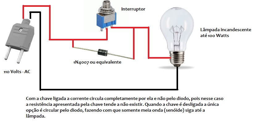
In the original article, I showed a very simple circuit using:
A switch + a diode + an incandescent lamp.
The idea was to use the diode to create an extremely simple two-level power control.
Sinusoidal waveform after passing through the diode (image)


Sinusoidal waveform after passing through the diode
In one position, the lamp receives the full sine wave.
In the other condition, the diode allows only one of the half-cycles to pass through.
This reduces the average power delivered to an approximately resistive load such as an incandescent lamp.
But Be Careful: This Does Not Apply to Every Lamp
The original article already included an important warning:
Do not use this idea indiscriminately with electronic lamps.
And today, I would expand that warning considerably.
A modern LED lamp, for example, usually contains an internal electronic power supply circuit.
Therefore, it should not be treated simply as a resistor.
Its behavior under half-wave power will depend on its internal circuit, and the manufacturer may not have designed it for this type of operation.
So we should not conclude:
“It worked with an incandescent lamp, so it will work with any device.”
That is not necessarily true.
A Resistive Load Is Different from an Electronic Load
A heating resistor or an old incandescent lamp behaves very differently from equipment containing:
Switching power supplies;
Motors;
Capacitors;
Transformers;
Electronic circuits.
Therefore, the effect of half-wave rectification must be analyzed according to:
The connected load.
A diode is not a “universal power reducer.”
What About a Soldering Iron?
In the original article, I also suggested this technique for obtaining two power levels in certain resistive soldering irons, especially higher-power models.
The principle is similar to that of the incandescent lamp when the heating element behaves essentially as a resistive load.
But once again, there is an important qualification:
This should not be generalized to soldering stations or soldering irons with internal electronic controls.
These devices must receive the power supply specified by the manufacturer.
The Diode Must Be Able to Handle the Current
We cannot choose just any diode simply because it:
“Allows current to flow in one direction.”
Every diode has limits.
One of them is its:
Maximum current rating.
If the load requires more current than the diode can handle, the component may overheat and fail.
Therefore, we need to know the load current.
The Diode Must Also Withstand the Reverse Voltage
During the half-cycle in which the diode is blocking current, it is subjected to a reverse voltage.
And there is a limit to this.
For this reason, another essential specification is the:
Maximum reverse voltage the diode can withstand.
If we exceed this limit, we may cause breakdown and destroy the component.
This is particularly important when working with high voltages.
127 V RMS Does Not Mean 127 V Peak
This concept is very important for anyone beginning to work with alternating current.
When we say that a power outlet supplies:
127 V AC,
we are normally referring to its:
RMS value.
For an ideal sine wave:
Vp = Vrms × √2
Therefore:
127 × 1.414 ≈ 180 V peak.
For 230 V RMS:
230 × 1.414 ≈ 325 V peak.
Therefore, components connected to the electrical mains must be rated according to the voltages actually present in the circuit, not just the number given as the nominal mains voltage.
A Diode Can Be the Starting Point of a Power Supply
Half-wave rectification also helps us understand how alternating current can be converted into direct current.
We start with:
Alternating voltage
↓
Rectification
↓
Pulsating voltage.
Then we can add a:
Filter capacitor.
It stores energy near the voltage peaks and supplies some of that energy to the load as the rectified voltage decreases.
The result is a voltage with less ripple.
But There Is a Better Solution: Full-Wave Rectification
If a single diode uses only one half-cycle, we can build a circuit capable of using:
Both half-cycles.
One of the best-known configurations uses:
Four diodes
forming a:
Bridge rectifier.
In this circuit, both the positive and negative half-cycles of the input contribute to producing current in the same direction through the load.
We then have:
Full-wave rectification.
Half-Wave vs. Full-Wave Rectification
We can summarize:
Half-wave
Uses only one of the half-cycles.
Full-wave
Uses both half-cycles.
For power supplies, full-wave rectification usually offers important advantages, including producing pulses at a higher frequency at the rectified output, making filtering easier.
In a 50 Hz electrical power system, for example:
Half-wave → pulses at 50 Hz
Full-wave → pulses at 100 Hz.
At 60 Hz:
Half-wave → 60 Hz
Full-wave → 120 Hz.
This Is Where We Begin to Understand a DC Power Supply
Notice how the concepts begin to connect.
We can start with:
Alternating current
↓
Transformer, when applicable
↓
Rectifier diodes
↓
Filter capacitor
↓
Regulation, when necessary
↓
Direct current for the circuit.
In other words, understanding the behavior of a single diode with a sine wave is one of the first steps toward understanding power supplies.
Be Careful with Experiments Connected Directly to a Power Outlet
The original circuit shows an application using mains voltage.
Today, I would add a much stronger warning:
I do not recommend that beginners perform this experiment directly on the electrical mains.
Mains voltages can cause serious or fatal electric shocks.
Furthermore, simply turning off a switch does not necessarily mean that every point in a circuit is safe to touch.
To learn the principle of rectification, it is much safer to use:
An isolated, low-voltage AC source suitable for experimentation.
For example, we can observe a low-voltage sine wave passing through a diode without having to work directly with the electrical mains.
The electronic phenomenon we want to study is the same.
An Oscilloscope Makes Everything Very Clear
If we have access to an oscilloscope and a safe, isolated setup, we can clearly visualize the phenomenon.
Before the diode:
Complete sine wave.
After the diode:
Only one set of half-cycles.
After adding filtering:
A voltage with less ripple.
This is an excellent experiment for understanding the difference between:
AC, pulsating DC, and filtered DC.
A Simple Component That Helps Us Understand So Much
A single diode operating with alternating current allows us to study:
Forward bias;
Reverse bias;
Sine waves;
Peak voltage;
RMS voltage;
Rectification;
Power;
Filtering;
Power supplies.
That’s why this seemingly simple circuit is so important for anyone learning electronics.
Summarizing How It Works
When we connect a diode in series with an AC source and a load:
1. During one half-cycle, the diode is forward-biased and conducts.
2. During the next half-cycle, it is reverse-biased and blocks current.
3. The load receives only one of the sine wave’s half-cycles.
4. The result is a half-wave rectified voltage.
5. The resulting waveform has different average and RMS values from the original sine wave.
6. With additional components, this pulsating voltage can be filtered and used to build a DC power supply.
This is how a component with only two terminals can completely transform the waveform present in a circuit.
Want to Learn More About Diodes and Electronics Applied to Audio?
Diodes appear in countless circuits: power supplies, protection circuits, rectifiers, signal limiters, and many other electronic projects.
And understanding why they work is much more useful than simply memorizing which direction they should be installed.
In my Electronics Applied to Audio Course, I focus precisely on building these fundamentals: electronic components, semiconductors, power supplies, amplifiers, and circuits used in real-world applications.
The goal is to move beyond:
“Connect this component here”
and reach the point where you can say:
“I understand what is happening to the voltage and current in this circuit.”
To continue exploring free content about diodes, semiconductors, electrical quantities, and other components, also visit the Electronics Fundamentals and Components section.