A power supply is one of the most interesting circuits for anyone starting to study electronics.
The basic principle is to convert the alternating voltage available from the electrical mains into a voltage suitable for powering a particular circuit or device.
In this project, I built a very simple power supply with an output intended mainly for slowly charging 12 V sealed batteries, such as those used in uninterruptible power supplies (UPS).
The assembly uses just a few components:
Transformer;
Diodes;
Capacitor;
Fuse;
On/off switch.
It is a simple circuit, but it provides an opportunity to understand several fundamental concepts in electronics.
Why Did I Build This Power Supply?
My main goal was to have a small power supply for slowly charging sealed batteries.
That’s why I used a transformer rated at:
12 V / 500 mA.
The relatively low current was intentional, as I wanted to perform a slow charge.
The same assembly also helps explain how a conventional power supply works.
Before You Start: Electrical Mains Safety
This project has an important difference compared with small circuits powered by disposable or rechargeable batteries:
The transformer is connected directly to the electrical mains.
This means working with potentially lethal voltage.
The part of the circuit connected to the mains must be completely insulated and protected inside a suitable enclosure.
Never handle the assembly while it is energized.
If you do not yet have experience working with mains voltage, use this project to understand the circuit, but carry out the assembly under the supervision of a qualified person.
Components Used
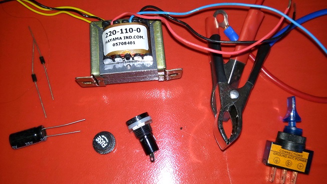
In the original build, I used:
- 1 × 12 V / 500 mA transformer;
- 1 × DPDT switch;
- 1 × fuse;
- 1 × fuse holder;
- 2 × 1N4007 diodes;
- 1 × 1000 µF / 25 V electrolytic capacitor;
- 2 × alligator clips for connecting to the battery.
We Can Divide the Power Supply into Stages
Instead of looking at all the components at once, we can think of the power supply in stages:
Electrical mains
↓
Transformer
↓
Rectification
↓
Filtering
↓
DC output
Each stage has a specific function.
Understanding this sequence is much more important than simply copying the connections.
The Transformer
The first component is the transformer.
It has two main sides:
Primary
and
Secondary.
The primary is connected to the electrical mains.
The secondary provides a lower voltage and is electrically isolated from the primary.
In my case, I used a transformer whose secondary provides:
12 V / 500 mA.
The Transformer’s 12 V Output Is AC
This detail is essential.
When we say that the transformer has a 12 V output, we mean:
12 V AC
or:
12 V alternating current.
We do not yet have a suitable DC output simply because the voltage has passed through the transformer.
We need another stage:
Rectification.
What Are the Diodes For?
Diodes allow current to flow predominantly in one direction.
This characteristic makes it possible to use them to convert an alternating voltage into a pulsating voltage with a single polarity.
In my build, I used:
2 × 1N4007 diodes.
The 1N4007 is a well-known rectifier diode frequently used in low-frequency power supplies.
Why Two Diodes?
Using two diodes is compatible with a full-wave rectifier configuration when the transformer has a center-tapped secondary.
In this arrangement, each diode conducts during part of the AC cycle.
The result is a rectified voltage that uses both half-cycles.
This differs from the familiar four-diode bridge rectifier, but the objective is similar:
To obtain a voltage with a defined polarity from an alternating voltage.
What Happens After Rectification?
After the diodes, we still do not have a perfectly steady DC voltage.
We have a pulsating waveform.
We can visualize it as:
Sinusoidal AC
↓
Rectification
↓
Pulsating DC.
To improve this voltage, we use a capacitor.
The 1000 µF Capacitor
In the power supply, I used an electrolytic capacitor rated at:
1000 µF / 25 V.
Its function is to help filter the rectified voltage.
During voltage peaks, the capacitor stores energy.
Between these peaks, it supplies some of that energy to the load.
This reduces voltage fluctuations at the output.
The Capacitor Works Like a Small Energy Reservoir
We can imagine an analogy with a water reservoir.
The inlet does not supply water continuously at the same rate.
The reservoir fills when the supply is greater and releases water when the supply decreases.
A capacitor does something conceptually similar in electrical terms:
It charges
and
discharges.
As a result, the voltage becomes less pulsating.
What Is Ripple?
Even after filtering, there is usually still some variation in the DC voltage.
This fluctuation is called:
Ripple.
The greater the current demanded by the load and the smaller the capacitance used, the greater this ripple tends to be, assuming all other conditions remain the same.
This is why the filter capacitor plays an important role in the power supply’s performance.
Pay Attention to the Polarity of the Electrolytic Capacitor
The capacitor used is polarized.
It has:
A positive terminal
and
a negative terminal.
It must be connected correctly.
Reversing an electrolytic capacitor in a power supply can damage it and create a dangerous situation.
Before powering up the circuit, check its polarity.
What Does 1000 µF / 25 V Mean?
These are two different specifications.
1000 µF represents the capacitance.
25 V represents the component’s specified maximum operating voltage.
We must not confuse these two quantities.
A capacitor rated at:
1000 µF / 25 V
does not “supply 25 V.”
It has a capacitance of 1000 µF and is rated to operate up to a specified maximum voltage.
The Output Is Not Necessarily Exactly 12 V DC
This is a very important point when studying power supplies.
A transformer rated at 12 V AC does not mean that, after the diodes and capacitor, we will obtain exactly:
12.00 V DC.
The AC voltage specified for a transformer normally corresponds to its root mean square, or RMS, value.
The peak value of a sine wave is higher.
We can approximate it as:
Vpeak ≈ Vrms × 1.414
For 12 V:
Vpeak ≈ 12 × 1.414
Vpeak ≈ 17 V
We then need to account for the voltage drops across the diodes and the circuit’s behavior under load.
Therefore, it is entirely possible to measure a filtered output voltage higher than the secondary’s nominal 12 V, especially with no load connected.
Voltage Also Varies with the Load
When no load is connected, we may measure a certain voltage.
When we start drawing current, the voltage may drop.
This depends on the:
Transformer;
Rectification;
Capacitor;
Current consumption.
That is why it is important to measure the power supply under the conditions in which it will actually be used.
This Power Supply Is Not Regulated
In the original build, I did not attempt to make a regulated power supply because it was not necessary for my intended application.
This means there is no regulator stage electronically maintaining a fixed output voltage.
We basically have:
Transformation + rectification + filtering.
Therefore, simply describing the output as “fixed 12 V” can be technically misleading.
The transformer is rated at 12 V, but the DC voltage after rectification and filtering depends on the operating conditions.
A Filtered Power Supply and a Regulated Power Supply Are Not the Same Thing
This distinction is important.
A power supply can be:
Rectified
and
filtered
without being:
Regulated.
Filtering reduces ripple.
Regulation aims to maintain the output voltage at a particular value despite variations within the expected operating conditions.
I did not include a regulator in this project.
Could We Add Voltage Regulation?
Yes, depending on the intended purpose of the power supply.
There are several ways to do this.
We can use:
Linear regulators;
Switching converters;
Adjustable regulator circuits.
However, adding regulation turns the project into a different type of power supply.
For understanding the fundamentals, this simple build is quite interesting.
The 500 mA Limit Comes Mainly from the Transformer
The transformer used was rated at:
12 V / 500 mA.
Therefore, we should not assume that we can connect any 12 V device simply because the voltage appears suitable.
Current also matters.
If a device requires:
2 A
this small power supply was not designed for that load.
The Correct Voltage Does Not Mean the Power Supply Is Suitable
Imagine two devices:
Device A → 12 V / 200 mA
Device B → 12 V / 2 A
Both operate at 12 V.
But their current requirements are completely different.
A power supply capable of powering the first device may not necessarily be able to power the second.
That is why we need to consider both:
Voltage
and
current.
The Fuse Is an Important Component
I also included:
A fuse
and
a fuse holder.
The fuse is a protective component.
When the current exceeds the conditions for which the system was designed, it can interrupt the circuit.
This helps reduce the consequences of certain faults.
The Fuse Should Not Be Chosen Randomly
Installing just any fuse we happen to find on the workbench is not good practice.
Its specifications must take into account:
The circuit’s normal operating current;
Inrush current;
The transformer’s characteristics;
Its installation position.
An oversized fuse may fail to provide the expected protection.
The On/Off Switch
I also used a DPDT switch to turn the power supply on and off.
The switch I used had a built-in LED, making it easy to see when the power supply was switched on.
It is a simple but very useful detail.
By looking at the enclosure, we can immediately tell whether the equipment is powered on.
I Installed the Switch and Fuse Holder in the Enclosure
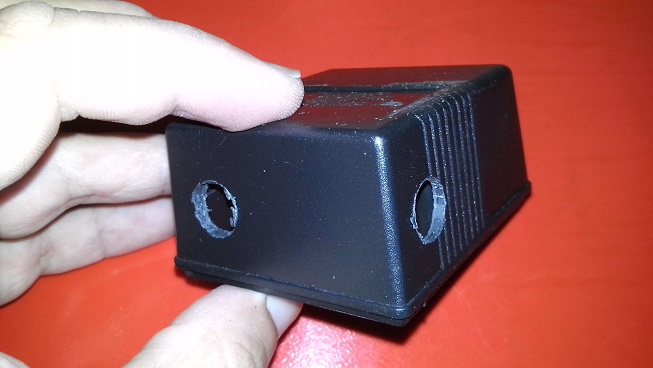
I drilled two holes in the Patola enclosure specifically for installing:
The switch
and
the fuse holder.
The components were then mechanically secured to the enclosure itself.
This is much better than leaving components connected to the electrical mains loose on the workbench.
Below, you can see that I assembled the entire unit inside a Patola-style enclosure. However, you can build your circuit wherever you prefer.
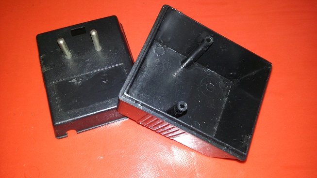
In the close-up below, we can see the two holes drilled in the small enclosure to accommodate the DPDT switch and fuse holder perfectly. The DPDT switch I used has a built-in LED that lights up when the switch is turned on, making it easy to see when the power supply is on.
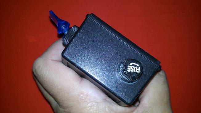
In the image below, you can see both the DPDT switch and the fuse holder installed in place.
After this step comes the circuit assembly. The circuit is very simple. In the images below, you can see the soldered circuit. Because of its simplicity, I used point-to-point wiring, also known as “spider wiring.” This means that the leads of one component are soldered directly to the leads of another component.
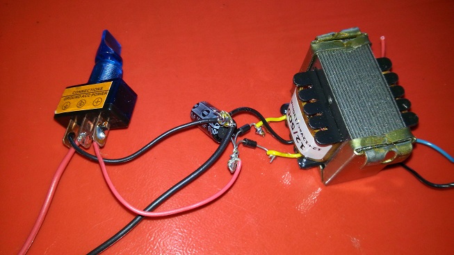
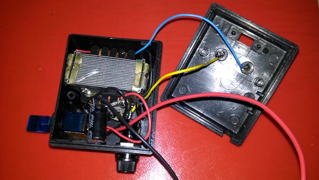
After that, all that remains is to place the entire circuit inside the enclosure and plug it into the wall outlet. Note that I did not install a switch to change the input voltage. The input voltage depends on the transformer, which has a primary winding rated for 110 V. I did not attempt to make the power supply regulated, since that was not necessary for my application.
The Enclosure Is Not Just for Appearance
The enclosure serves an extremely important safety function.
Inside the power supply, there are points connected to the electrical mains.
These points must not be accessible during normal use.
The enclosure also protects:
Wires;
Solder joints;
Components;
Connections.
A circuit connected to the electrical mains should never be left exposed on a table during use.
I Used Point-to-Point Wiring
Because the circuit has very few components, I did not use a printed circuit board.
I used a technique commonly known as:
Spider wiring.
The component leads are soldered directly to one another.
For small experimental circuits, this technique can be quite practical.
Spider Wiring Does Not Mean Disorganized Wiring
Even without a circuit board, we need to ensure:
Mechanically secure connections;
Proper insulation;
Adequate spacing between connection points;
Correct polarities.
And, most importantly in this project, we need to keep the section connected to the electrical mains properly protected.
Physically Separate the Primary and Secondary Sides
This is an important practice in any assembly involving a transformer.
On one side, we have the section connected to the electrical mains:
AC input → fuse → switch → primary winding.
On the other side, we have the low-voltage section:
Secondary winding → diodes → capacitor → output.
Keeping these sections physically separated improves the safety of the assembly.
The Transformer Also Provides Isolation
A conventional transformer suitable for this type of application provides galvanic isolation between its primary and secondary windings.
This means the output is not simply a direct electrical connection to the mains.
This isolation is one of the reasons why the transformer is so important in this type of power supply.
My Power Supply Was Built for a Specific Mains Voltage
In the original build, I did not install a voltage selector switch.
The transformer I used had a primary winding designed for 110 V.
Therefore, this original assembly should not simply be connected to a mains supply with a different voltage.
This detail is especially important today, when the same content may be accessed by people in different countries and regions.
Always Check Your Mains Voltage
Before using any transformer, check the specifications of its primary winding.
Transformers may be designed for different voltages or have windings that allow specific configurations.
Never assume that:
“It’s a 12 V transformer, so I can plug it into any outlet.”
The 12 V rating refers to the secondary winding.
The primary winding must be compatible with the electrical mains being used.
How Do You Test a Power Supply After Assembly?
Before connecting any battery or device, the first test should be performed with no load.
With the multimeter set to the appropriate range, we can check the output.
Confirm:
Polarity;
DC voltage;
Apparent stability.
If the measured value is very different from what you expected, switch off the power supply and check the assembly.
Then We Can Test It with a Suitable Load
Measuring the output without a load is not enough to fully evaluate a power supply.
We can connect a known load and observe:
Voltage;
Current;
Transformer heating;
Overall behavior.
This helps identify problems before connecting a more valuable device.
Alligator Clips Make Connection Easier
Since my main application was connecting the power supply to batteries, I used:
Two alligator clips.
These make it easier to connect the power supply terminals to the battery terminals.
However, there is one essential precaution:
Polarity.
Clearly Identify Positive and Negative
Do not rely on memory alone.
Use clear visual identification.
Before connecting a battery, check:
Power supply positive → battery positive
Power supply negative → battery negative.
Reversing the connections can cause damage and high currents.
Be Very Careful When Calling a Simple Power Supply a “Battery Charger”
There is an important distinction here.
A simple DC power supply is not automatically a suitable charger for every type of battery.
Each battery chemistry has its own charging requirements.
There are batteries such as:
Lead-acid;
NiCd;
NiMH;
Li-ion;
LiPo;
LiFePO4.
Their charging methods are different.
Do Not Use This Assembly to Charge Lithium Batteries
Lithium batteries require proper charging control.
A simple power supply consisting of a transformer, diodes, and a capacitor should not be treated as a substitute for a dedicated charger for:
Li-ion
or
LiPo.
The original project was intended for sealed batteries such as those found in uninterruptible power supplies (UPS).
Even Sealed Batteries Require Care
The battery must be compatible with the:
Applied voltage;
Current;
Charging method;
Charging time.
The idea that “slow charging is always safe” should not be treated as a universal rule.
The battery manufacturer’s specifications must take precedence.
The Transformer’s Rated Current Is Not a Charge Controller
Another important point when revisiting this project is understanding that a 500 mA transformer does not necessarily mean:
“The battery will receive exactly 500 mA throughout the entire charging process.”
The actual current will depend on the circuit and the voltage differences involved.
Therefore, a properly controlled charger requires a circuit topology specifically designed for the battery being used.
As an Educational Project, However, This Power Supply Teaches Us a Lot
We can observe practically the entire fundamental sequence of a simple linear power supply:
Transformation
↓
Rectification
↓
Filtering
↓
Powering the load.
And we can associate each stage with real components.
We Can Measure the Voltage Before and After the Diodes
With appropriate safety procedures, we can study the transformer’s secondary winding.
Before rectification, we have:
Alternating voltage.
After rectification:
Pulsating voltage with a defined polarity.
After the capacitor:
DC voltage with less ripple.
This is an excellent experiment for understanding what the diagrams in textbooks illustrate.
It Gets Even More Interesting with an Oscilloscope
We can visualize the waveforms at different points in the isolated low-voltage section, provided that the procedure and measuring equipment are appropriate.
First, we see a sine wave.
Then, we see the rectified waveform.
Finally, we observe the effect of the capacitor.
In this way, concepts such as:
AC;
DC;
Rectification;
Filtering;
Ripple
stop being just theory.
The Capacitor Visibly Changes the Waveform
If we examine the rectified circuit without filtering and then add the capacitor, we can clearly see its function.
This type of experiment is extremely interesting because it shows that the capacitor is not there simply because “the schematic says to install one.”
It has a specific purpose.
We Can Also Study the Voltage Drop Across the Diodes
A real diode does not behave like an ideal component.
When it conducts, there is a voltage drop across it.
We can measure this difference and relate it to the voltage observed at the output.
This helps us begin to understand that real components have characteristics that must be considered when designing circuits.
We Can Study the Effect of the Load
Another interesting experiment is to compare:
Power supply without a load
with:
Power supply with a load.
The voltage may change.
Ripple may increase.
The transformer may become hotter.
All of this helps us understand that a power supply must be designed with its intended load in mind.
A Power Supply Does Much More Than “Convert 110 V into 12 V”
The transformer performs only one of the stages.
A conventional DC power supply may involve:
Voltage reduction or transformation;
Isolation;
Rectification;
Filtering;
Regulation;
Protection.
In this project, we use a very simple version of this process, without a voltage regulation stage.
Why Start with a Simple Power Supply?
Because it brings together basic components found in countless electronic devices.
When we open an older electronic device, we frequently find:
A transformer;
Diodes;
Capacitors.
If we understand this small power supply, we begin to recognize similar stages in much larger circuits.
A Power Supply Is an Excellent Introduction to Electronics
With just a few components, we can study:
Alternating voltage;
Direct voltage;
Transformers;
Diodes;
Capacitors;
Current;
Power;
Fuses;
Electrical safety.
It is difficult to find such a simple circuit that brings together so many fundamental concepts.
How My Assembly Turned Out
After installing the switch and fuse holder, I assembled the circuit using the spider-wiring technique and placed everything inside the Patola enclosure.
The original power supply was based on:
12 V / 500 mA transformer;
Two 1N4007 diodes;
1000 µF / 25 V capacitor;
Fuse;
On/off switch;
Alligator clips at the output.
I did not add a voltage regulator because it was not necessary for my intended application at the time.
A Simple Project That Helps You Understand Much Larger Circuits
Once we understand this power supply, we can move on to projects featuring:
Bridge rectifiers;
Larger capacitors;
Linear regulators;
Short-circuit protection;
Current limiting;
Adjustable output;
Voltmeter and ammeter.
But the underlying principle still begins with the same basic stages.
That is exactly what makes this small project interesting.
You can look at a finished power supply and see nothing more than a box.
Or you can understand that:
The transformer reduces the voltage and provides isolation;
The diodes rectify;
The capacitor filters;
The fuse provides protection;
The load receives the energy.
When we begin to see electronics this way, circuits that initially seem complicated become much easier to understand.
Want to Learn Electronics by Understanding What Really Happens Inside Circuits?
Building a power supply like this is a great way to see how components studied individually begin to make much more sense when they work together.
Transformers, diodes, capacitors, resistors, transistors, and integrated circuits form the fundamental building blocks of countless electronic devices.
In the Electronics Applied to Audio Course, these components are studied in a practical way, connecting the fundamentals of electronics with power supplies, amplifiers, and other circuits found in audio equipment.
The goal is to help you move beyond simply copying schematics and start understanding the power supply path, the signal path, and the function of each component within an electronic circuit.
To continue exploring free content about power supplies, rectification, filtering, regulators, converters, and power supply projects, visit the Power Supplies section.