Audio signal amplification is one of the best-known applications of transistors. To understand how this works, it is important to know some of the characteristics of transistors, their biasing methods, and some of the components used in amplifier circuits.
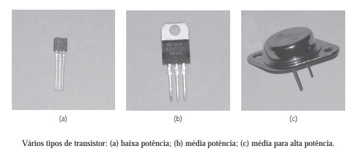
Transistors can be found in different packages and power ratings. There are low-power transistors, mainly used to handle low-level signals, and power transistors, designed to withstand higher levels of current, voltage, and power dissipation within the limits specified by the manufacturer.
Small-signal transistors normally dissipate little power during operation. This does not mean that they cannot heat up, but under the normal operating conditions for which they were designed, power dissipation is usually low.
Power transistors, on the other hand, are designed to operate in situations where power dissipation can be considerably higher. Therefore, depending on the application, heat sinks may be required.
The 2N3055 Transistor
A well-known transistor used in power circuits is the 2N3055.
This transistor has a TO-3 metal package, and when looking at it, we can see only two insulated terminals on the bottom. This may seem unusual because we know that a BJT has three terminals: base, collector, and emitter.
In the 2N3055, the metal package itself is electrically connected to the collector, serving as the third terminal.
It is important to note that this is not simply because the collector is “the part that gets the hottest.” Heat is generated within the semiconductor device during operation and must be conducted from the junction to the package and, when necessary, to a heat sink.
Transistor Current Gain
One of the important characteristics of a BJT is its current gain.
This gain can be represented by βDC or hFE and, in simplified terms, relates the collector current to the base current:
βDC = IC / IB
Thus, by knowing the approximate current gain and the current applied to the base, we can estimate the collector current while the transistor is operating in the appropriate region.
However, it is important to understand that hFE is not a fixed value.
When looking at a transistor datasheet, we usually find a range of values. The gain can vary from one transistor to another and also depends on factors such as collector current and temperature.
Therefore, when designing a circuit, we should not assume that two transistors of the same model will necessarily have exactly the same gain.
How to Test a Transistor with a Multimeter
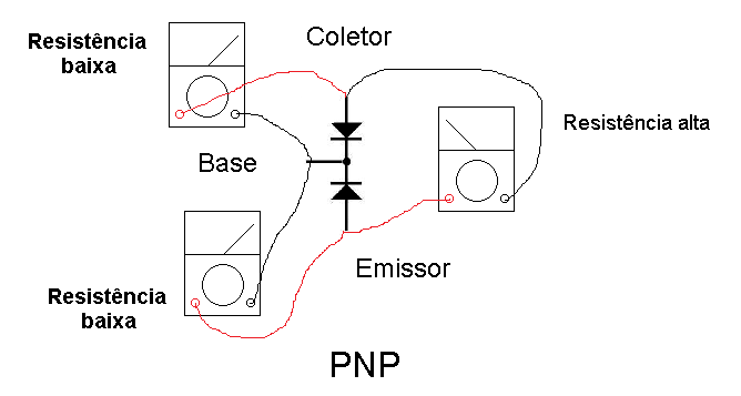
We can understand a BJT in a simplified way by thinking of its internal structure as two PN junctions.
This characteristic allows us to perform some tests using a multimeter.
With modern digital multimeters, the recommended method is to use the diode test function.
For an NPN transistor in good condition, placing the positive probe of the multimeter on the base should produce a voltage drop typical of a silicon junction when the negative probe is placed first on the emitter and then on the collector.
When the probes are reversed, there should normally be no significant conduction through these junctions.
For a PNP transistor, the polarities used in the test are reversed.
We can also check the path between the collector and emitter. In a standard BJT, when tested out of circuit and with no current applied to the base, we normally do not expect significant conduction between the collector and emitter.
This test is useful for identifying certain faults, particularly shorted transistors, but it does not replace a complete analysis of the component under its actual operating conditions.
Amplifier Classes
Amplifiers can be classified according to the way their active devices conduct the signal.
Among the best-known classes are Class A, Class B, and Class AB.
Each has different characteristics in terms of biasing, efficiency, and distortion.
Class A Amplifier
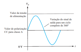
In Class A, the transistor remains conducting throughout the entire signal cycle, meaning that it has a conduction angle of approximately 360 degrees.
To achieve this, the transistor is biased so that it remains in its active region even when no audio signal is applied to the input.
This characteristic makes it possible to amplify the entire signal cycle using the same device and avoids the crossover distortion characteristic of certain Class B stages.
The disadvantage is its low efficiency.
Even when there is no input signal, the transistor continues to conduct current and dissipate power. As a result, a considerable portion of the energy supplied by the power source is converted into heat.
The theoretical maximum efficiency depends on the configuration used. In a Class A stage with a resistive load, for example, the theoretical maximum efficiency is relatively low, reaching approximately 25%.
This explains why Class A amplifiers normally require special attention to thermal dissipation.
Class B Amplifier
In Class B, the device is biased to conduct for approximately half of the signal cycle, or about 180 degrees.
In a complementary output stage, two transistors can be used: one operates predominantly during the positive half-cycle and the other during the negative half-cycle.
This configuration offers higher efficiency than Class A.
However, there is a problem in the region where the signal crosses zero.
Silicon transistors require a certain base-emitter voltage before significant conduction begins. In a complementary Class B stage, this can create a small region near the zero crossing where neither transistor conducts adequately.
The result is a deformation of the signal known as crossover distortion.
Therefore, it is not exactly that the transistor “does not interpret” signals between 0 V and 0.7 V. The issue lies in the way the base-emitter junctions of the transistors begin to conduct in the region near the signal’s zero crossing.
Class AB Amplifier
Class AB attempts to combine some of the characteristics of Classes A and B.
In this case, the transistors are biased so that they conduct for slightly more than half of the cycle. As a result, the conduction angle is between 180 and 360 degrees.
This small overlap between the conduction of the devices helps reduce the crossover distortion found in an ideal Class B stage.
For this reason, Class AB is widely used in audio amplifiers, offering an attractive compromise between efficiency and low distortion.
Capacitors in Audio Circuits
Capacitors are very important components in amplifier circuits.
There are different types of capacitors, classified according to characteristics such as dielectric material, manufacturing technology, construction, and application.
Many capacitors used in electronics do not have a defined polarity. However, some types are polarized, including most aluminum electrolytic capacitors.
There are also electrolytic capacitors specifically designed for applications without a defined polarity, known as bipolar or non-polarized capacitors.
Therefore, it is important to always check the characteristics of the component being used.
Coupling Capacitor
A very common application of capacitors in amplifier circuits is coupling between stages.
A coupling capacitor allows the AC component corresponding to the audio signal to pass while blocking the DC component between different points in the circuit.
This is important because each stage may have its own DC bias conditions.
A capacitor should not literally be understood as a short circuit for any AC signal.
Its opposition to alternating current is called capacitive reactance, and it depends on frequency and capacitance:
Xc = 1 / (2πfC)
The higher the frequency or capacitance, the lower the capacitive reactance.
Therefore, the value of the coupling capacitor should be selected by taking into account the circuit impedance and the lowest frequency that we want to transmit adequately.
Guitar Frequencies
When working with amplifiers for musical instruments, we need to consider the frequency range we want to reproduce.
In the case of a guitar in standard tuning, the fundamental frequency of the low E string is approximately 82 Hz.
This means that we cannot consider, for example, 1 kHz to be the lowest frequency of interest for a guitar.
In addition to the fundamental frequencies produced by the strings, the signal contains various harmonics, which extend to much higher frequencies and have a significant influence on the instrument’s tone.
Therefore, when selecting the coupling capacitors for a guitar amplifier, we need to take into account both the instrument’s lowest frequencies and the range of harmonics we want to preserve.
A cutoff frequency of 100 Hz, for example, is already above the fundamental frequency of the low E string, which is approximately 82 Hz. Depending on the purpose of the circuit, this may cause some attenuation of the lower frequencies.
Decoupling Capacitor
Another important application is the power supply decoupling capacitor.
This capacitor helps reduce noise, rapid voltage fluctuations, and unwanted signals present on the power supply line.
Under certain conditions, an amplifier may exhibit low-frequency oscillations known as motorboating. This phenomenon may be related to unwanted feedback through the power supply and inadequate decoupling between stages.
The decoupling capacitor helps provide a low-impedance path for certain AC components and transients present on the power supply line.
However, it should not be understood as a solution for a depleted cell or battery. If the power source cannot provide the voltage and current required by the circuit, the power supply problem itself must be addressed.
Capacitor in Parallel with the Emitter Resistor
In some amplifiers, we find a capacitor connected in parallel with the transistor’s emitter resistor.
The emitter resistor is important for stabilizing the transistor’s operating point, but it also introduces a form of negative feedback that reduces the stage gain for AC signals.
By placing a capacitor in parallel with this resistor, we can reduce this feedback at frequencies where the capacitor’s reactance is sufficiently low.
This allows us to increase the voltage gain of the stage for the audio signal, without simply eliminating the stabilizing effect of the emitter resistor on the DC bias.
Therefore, the increase in gain does not occur simply because the capacitor “lowers the input impedance.” Its main effect is to reduce emitter degeneration or negative feedback for the AC signal.
Heat Dissipation in Transistors
When a transistor operates in an amplifier, part of the electrical power may be converted into heat.
In a simple approximation for a BJT, a significant portion of this dissipation can be estimated by:
P ≈ VCE × IC
where VCE is the voltage between collector and emitter and IC is the collector current.
This means that a transistor can dissipate a considerable amount of power when there is simultaneously a significant voltage between collector and emitter and a high current flowing through the device.
Heat is generated in the active region of the semiconductor, and a very important parameter is the junction temperature, usually indicated as Tj.
This temperature must not exceed the maximum limit specified by the manufacturer.
Heat Sink
When the power dissipated by the transistor is high, the package itself may not be sufficient to transfer the heat to the environment.
In this case, we use a heat sink.
The purpose is to facilitate the transfer of heat generated in the transistor to the environment, keeping the junction temperature within safe limits.
A thermal paste or thermal compound may also be used between the transistor and the heat sink.
Its purpose is to fill small irregularities in the contact surfaces, reducing the thermal resistance between the component package and the heat sink.
There are different types of thermal compounds, with different formulations and characteristics. Therefore, they do not necessarily need to have a specific color or composition.
Depending on the package and the circuit, it may also be necessary to use electrical insulators between the transistor and the heat sink, especially when a metallic part of the package is electrically connected to one of the transistor terminals.
Understanding Audio Signal Amplification
Audio amplification involves much more than simply increasing the amplitude of a signal.
When analyzing an amplifier, we need to understand transistor biasing, its operating class, gain, coupling and decoupling capacitors, frequency response, and the thermal dissipation of the components.
Understanding these concepts helps not only to build existing circuits, but also to identify problems, make modifications, and develop new projects.
It is precisely this practical understanding of components and circuits that allows us to advance in the study of Audio Electronics and explore specific topics in greater depth in Amplifiers and Vacuum Tube Electronics.
Bibliographic References
BOYLESTAD, Robert; NASHELSKY, Louis. Dispositivos eletrônicos e teoria de circuitos. 11th Edition: São Paulo: Pearson, 2013.
BORTONI, Rosalfonso. Amplificadores de Áudio. 1st Edition: Rio de Janeiro: H Sheldon, 2002.
CARVALHO, Antônio Carlos Lemos; SILVA, Davinson Mariano. Laboratório de eletrônica analógica e digital. 1st Edition: São Paulo: Senai SP, 2015.
MALVINO, Albert; BATES, David. Eletrônica. 7th Edition: Porto Alegre: Mc Graw Hill, 2007.
SADIKU, Matthew; ALEXANDER, Charles. Fundamentos de circuitos elétricos. 5th Edition: Porto Alegre: Mc Graw Hill, 2013.