Tube amplifiers continue to attract a great deal of interest among musicians, guitarists, and audio electronics enthusiasts.
Even with all the advances in transistor and digital amplifiers, vacuum tubes are still used in many devices designed primarily for guitars.
There is a simple reason for this:
tube circuits have their own operating characteristics and produce a sound response that differs from that found in a transistor amplifier.
It was precisely my interest in this type of circuit that led me to build a small amplifier based on the classic Fender Champ 5C1.
The project uses only a few components and just two tubes in the amplification path:
6SJ7 in the preamplifier
and
6V6 in the power stage.
The result is a small tube amplifier of approximately 5 watts, with a tone that I find particularly interesting for Blues and Rock.
What is the Fender Champ 5C1?
The Fender Champ is a family of small guitar amplifiers.
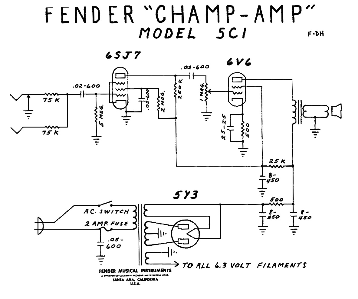
The 5C1 circuit belongs to the early generations of the Champ and uses an extremely simple architecture.
In the project I built, we basically have:
guitar input
↓
6SJ7 tube
↓
6V6 tube
↓
output transformer
↓
speaker
In addition, there is naturally a power supply responsible for providing the different voltages required by the circuit.
What is particularly interesting is the small number of components used in this amplifier.
Why Build a Tube Amplifier?
We can simply buy a ready-made amplifier.
But for those who enjoy electronics, building an amplifier offers a different experience.
During the build, we begin to understand topics such as:
preamplification;
power amplification;
biasing;
transformers;
filaments;
rectification;
filter capacitors;
coupling between stages;
speakers.
In other words, the amplifier stops being a closed box and becomes a set of building blocks that we can study separately.
Tubes Behave Differently from Transistors
A tube and a transistor can both be used to amplify signals, but they are very different devices.
In a bipolar transistor, we normally find:
base;
collector;
emitter.
In a tube, on the other hand, we can find elements such as:
cathode;
grid;
plate;
as well as other grids, depending on the type of tube.
These physical and electrical differences result in circuits with very different characteristics.
What Is a Vacuum Tube?
A vacuum tube uses the movement of electrons inside an evacuated enclosure to control electric current.
One of the first important elements is the cathode.
It needs to be heated.
That is why we also have the:
filament circuit.
When the assembly reaches its operating temperature, electrons are emitted.
These electrons can be controlled by the different internal elements of the tube.
Thus, a small signal applied to the control circuit can modify a much larger current.
It is precisely this principle that makes it possible to use the tube for amplification.
Both Tubes Used in My Champ Have 6.3 V Filaments
In the amplifier I built, both the 6SJ7 and the 6V6 have filaments powered by 6.3 volts.
This voltage comes from a separate winding in the power transformer.
Therefore, the transformer does not only supply the high-voltage section of the circuit.
It also needs to provide the appropriate voltage for the filaments.
Why Do We Need the Filament?
Without proper heating, the tube cannot operate normally.
That is why, when we turn on a tube amplifier, we can observe the filaments beginning to heat up.
Depending on the tube and its construction, we may even see a small internal glow.
This is part of the component’s normal operation.
The 6SJ7 Handles the Preamplification
The first tube used in my circuit is the 6SJ7.
It operates in the preamplifier stage.
The signal coming from the guitar is relatively small.
Therefore, before it reaches the power stage, we need to amplify it.
We can represent this as:
Guitar
↓
Low-amplitude signal
↓
6SJ7
↓
Amplified signal
↓
6V6
The 6SJ7 is responsible for this first stage of amplification.
The 6V6 Is the Power Tube
After the preamplifier stage, the signal reaches the 6V6.
It serves as the output tube, meaning that it is responsible for the amplifier’s power stage.
Now we are not simply increasing the amplitude of a small signal.
We need to provide enough energy to drive the speaker.
This is precisely where the power stage comes into play.
Both Tubes Are Pentodes
Both the 6SJ7 and the 6V6 used in this circuit are pentodes.
The name is related to the number of active internal elements in the tube.
A pentode has five main elements.
This construction provides characteristics that differ from simpler tubes, such as triodes.
What Is a Triode?
A triode has three main elements:
cathode;
control grid;
plate.
It is one of the classic configurations used for amplification.
There are also tubes known as dual triodes, which contain two similar systems within the same envelope.
A very well-known example in audio electronics is the:
12AX7.
The Fender Champ 5F1 Uses a Different Configuration
There is another very well-known Fender Champ circuit, the 5F1.
This model uses a different configuration, with a dual-triode tube such as the 12AX7 in the preamplifier.
This is interesting because it shows that apparently similar amplifiers can use different architectures.
Changing the preamplifier tube also means changing the way the circuit needs to be designed.
My 6SJ7 Has an Interesting Feature
The 6SJ7 tube I used does not have the traditional appearance of an all-glass tube.
It has a shielded metal construction.
In the original article, I specifically mentioned this more robust construction and its lower susceptibility to external interference.
Visually, it stands out because it is quite different from the glass tubes we normally associate with guitar amplifiers.
The Power Stage Uses Only One 6V6
This is another very interesting aspect of the project.
There is only one power tube.
This configuration is known as single-ended.
We can think of it as:
Preamplifier
↓
a single power tube
↓
output transformer
↓
speaker.
It is a relatively simple architecture and very interesting for anyone who wants to study tube amplification.
What Is a Single-Ended Amplifier?
In a single-ended configuration, a single power device handles the entire signal in the stage.
This differs from a push-pull circuit, in which we normally use two devices working in a complementary manner during different parts of the signal cycle.
Therefore:
single-ended → one main output tube
while:
push-pull → normally two output tubes working together.
The Champ 5C1 offers an excellent opportunity to study a simple single-ended architecture.
The Amplifier Delivers Approximately 5 Watts
The circuit’s output power is around 5 watts.
Anyone accustomed to modern amplifiers advertised with dozens or hundreds of watts might think:
“5 W is very little.”
But electrical power and perceived volume do not have a simple linear relationship.
In addition, for guitar, the behavior of the amplifier when it begins to saturate is an important part of the tone itself.
A Small Tube Amplifier Can Produce Plenty of Volume
Five watts through a suitable speaker can produce a considerable amount of volume in smaller environments.
It is enough for:
practice;
recording;
rehearsing under certain conditions;
experimenting with different tones.
And there is another option commonly used in live performances:
miking the amplifier.
We Can Mic a Small Amplifier
This was actually an observation I made in the original article.
Even a low-power amplifier can be used in rehearsal or live performance situations by placing a microphone in front of the speaker and sending that signal to the PA system.
We have:
Guitar
↓
Amplifier
↓
Speaker
↓
Microphone
↓
Mixer
↓
PA
This way, the amplifier can be chosen primarily for its tone, while the PA system is responsible for reproducing that sound on a larger scale.
The Amplifier Directly Contributes to the Guitar’s Tone
When we think about tone, we cannot analyze only the instrument.
We have a signal chain:
guitar
↓
pickups
↓
pedals, when used
↓
amplifier
↓
speaker
↓
room.
Each stage affects the final result.
That is why two different amplifiers can make the same guitar sound very different.
My Champ 5C1 Does Not Have an Extremely Clean Sound
This is one of the characteristics I really liked about this circuit.
In the original article, I described the sound as a little “nervous.”
Do not expect that completely clean and crystal-clear sound even when we turn up the volume.
The amplifier has a slightly rougher character, which I found particularly interesting for:
Blues
and
Rock.
What Happens When We Turn Up the Volume?
In a simple tube amplifier, when we increase the signal sufficiently, the stages begin to move out of their most linear operating region.
The waveform begins to change.
This produces:
distortion;
harmonics;
compression;
changes in dynamics.
In a hi-fi amplifier, we often want to minimize these changes.
With guitar, the situation is different.
Amplifier distortion can be part of the desired sound itself.
This Explains Why Guitarists Like Small Amplifiers
In an extremely powerful amplifier, a very high volume may be required to drive the power stage into certain saturation conditions.
In a small tube amplifier, we can achieve this behavior with less absolute power.
That is why small tube amplifiers remain very interesting for recording and experimenting with different tones.
I Modified the Rectifier Stage
The original 5C1 circuit uses a 5Y3 rectifier tube.
In my build, I made a modification:
I removed the 5Y3 and used two solid-state 1N4007 diodes for rectification.
Thus, my amplifier uses only two tubes in the audio circuit:
6SJ7
and
6V6.
What Is Rectification For?
The energy we receive from the transformer is alternating current.
But certain parts of the amplifier need to operate with direct current.
Therefore, we need to convert:
AC
into:
DC.
That is precisely the function of the rectifier stage.
After rectification, we also use capacitors and other components to filter and smooth the voltage.
Tube Rectification
In the original circuit, this task is performed by the 5Y3 tube.
It works as a rectifier.
Historically, this type of solution was widely used because modern semiconductors simply did not exist when many of these amplifiers were designed.
Rectification with Silicon Diodes
In my build, I used two 1N4007 diodes.
They are solid-state diodes.
They make it possible to perform rectification with components that are much smaller than a rectifier tube.
This was the main modification I made compared with the original 5C1 circuit.
Replacing the Rectifier Tube Changes the Behavior of the Power Supply
It is important to understand that replacing a rectifier tube with silicon diodes does not simply mean replacing one large component with two small ones.
The devices have different electrical characteristics.
This can affect:
voltage drop;
resulting DC voltage;
power supply behavior under load.
Therefore, a modification of this type needs to take into account the actual voltages obtained in the circuit.
A Tube Amplifier Operates with High Voltages
This point requires a great deal of attention.
Although the filaments may operate at only 6.3 V, other points in a tube amplifier may have hundreds of volts.
And these voltages may remain present even after the equipment has been turned off, due to the energy stored in the power supply capacitors.
Therefore, building or repairing a tube amplifier requires proper knowledge and safety procedures.
Unplugging It Does Not Necessarily Mean There Is No Voltage
The filter capacitors can retain an electrical charge.
Therefore, we can turn off the equipment, unplug it from the wall, and still find dangerous voltage inside the chassis.
Never put your hands inside a tube circuit simply because it is turned off.
Before working on it, you must measure and make sure that conditions are truly safe.
The Power Transformer Plays a Fundamental Role
In my amplifier, the transformer needs to provide the voltages required by the different circuits.
We have at least:
a 6.3 V filament winding
and
a winding intended for the high-voltage supply.
This shows why we cannot simply use any available transformer.
It needs to be appropriate for the project.
There Is Also an Output Transformer
The power tube should not simply be connected directly to a conventional speaker.
Between the 6V6 and the speaker, we use an output transformer.
This component is essential in tube amplifiers.
Its function is related to matching the electrical conditions between the power stage and the speaker.
Why Is the Output Transformer Necessary?
The tube naturally operates under voltage and impedance conditions that are very different from those found in a speaker.
The transformer makes this matching possible.
In simplified form:
6V6 Tube
↓
Output Transformer
↓
Speaker
Without the proper component, the stage would not operate correctly with the load.
The Output Transformer Also Influences the Result
In a tube amplifier, the output transformer should not be treated simply as just another component.
Its electrical characteristics influence the operation of the power stage.
We need to consider parameters such as:
primary impedance;
secondary impedance;
power;
frequency response.
This is another example of how an amplifier is a complete system.
I Did Not Use a Printed Circuit Board
Another interesting characteristic of my build is that I did not make a PCB.
I used terminal strips and built the circuit using a technique known as:
point-to-point wiring.
This type of construction works very well with tube circuits.
What Is Point-to-Point Wiring?
In point-to-point construction, components and wires are connected directly between physical terminals.
We can have:
tube socket terminal
↓
resistor
↓
terminal strip
↓
capacitor
↓
another point in the circuit.
There is not necessarily a printed circuit board connecting everything through copper traces.
Old Amplifiers Often Used This Type of Construction
Before printed circuit boards became widespread, it was common to find electronic equipment assembled using:
sockets;
terminals;
wires;
directly connected components.
In the original article, I specifically mentioned that old tube amplifiers used this type of construction.
Point-to-Point Wiring Is Visually Interesting
When we open an amplifier built this way, we can practically follow the circuit.
We see:
resistor;
capacitor;
wire;
tube socket terminal;
transformer.
For someone learning electronics, this can be very interesting because it makes it easier to relate the schematic to the physical construction.
But Organization Is Essential
Point-to-point wiring does not mean simply placing wires randomly.
In audio circuits, the physical arrangement of components affects:
noise;
interference pickup;
unwanted feedback;
stability.
Therefore, we need to think carefully about the layout.
Filament Wiring Requires Attention
The filaments operate with alternating current.
This supply can contribute to noise if the wiring is poorly positioned.
For this reason, in tube amplifier builds, the arrangement of the filament wires usually receives considerable attention.
A common practice is to keep certain pairs of wires twisted and positioned in a planned manner inside the chassis.
The Amplifier Input Is a Sensitive Area
The signal coming from the guitar has a relatively small amplitude.
Therefore, the area near the input and the first stage is particularly sensitive to noise pickup.
As we move through the amplifier, the signal amplitude tends to increase.
For this reason, a good layout seeks to prevent power and supply sections from interfering with low-level signal sections.
The Chassis Helps with Shielding
An amplifier normally uses a metal chassis precisely because it can help with electrical protection and electromagnetic shielding.
In my build, however, I decided to use something quite different.
I Used a Cake Pan as a Chassis
Yes.
The chassis of my Fender Champ was made using an aluminum cake pan.
It is a very homemade solution, but it worked very well for the experimental build.
The major advantage was how easy the material was to work with.
Aluminum Is Very Easy to Cut and Drill
To install a tube circuit, we need to make several openings for:
tube sockets;
transformers;
connectors;
potentiometers;
screws;
cables.
In the aluminum pan, these cuts and holes are relatively easy to make. This ease of working with the material was precisely one of the reasons I used it.
But a Cake Pan Is Not the Perfect Chassis
In the original article itself, I make one reservation:
for good shielding, it is not necessarily the most suitable solution.
It worked very well as an experimental chassis and allowed for a practical build.
But an enclosure specifically designed for amplifiers may offer mechanical and electrical advantages.
Planning the Holes Before Cutting Prevents Problems
If you are building any equipment in a metal chassis, it is worth making a layout first.
Place on the chassis:
power transformer;
output transformer;
tubes;
potentiometers;
connectors.
See whether everything fits.
Then think about the interior.
Only then mark the holes.
Once the aluminum has been cut, changing the position of a tube is no longer simple.
Transformers Also Need to Be Positioned Carefully
Transformers produce magnetic fields.
In an audio amplifier, we need to prevent these fields from being picked up unintentionally by sensitive parts of the circuit.
Therefore, the relative position between the:
power transformer
and
output transformer
can affect the equipment’s noise level.
A good layout begins before the first solder joint.
Grounding Is Another Critical Point
An amplifier can be electrically correct on paper and still produce a lot of noise because of the way the grounds are arranged.
We have several current return paths:
power supply;
preamplifier;
power stage;
input;
filaments, depending on the configuration.
The way these paths are arranged affects the behavior of the circuit.
The Famous 50/60 Hz Hum
A classic problem in amplifiers is that continuous low-frequency noise:
HMMMMMMMM…
It can have several causes.
Among them:
inadequate power supply filtering;
grounding;
transformer placement;
wiring;
shielding.
Diagnosing these problems is part of the learning process when building amplifiers.
Power Supply Capacitors Help Filter the Voltage
After rectification, the voltage does not automatically become perfectly smooth DC.
We need filtering.
Capacitors are used to reduce the ripple present in the rectified voltage.
This is another demonstration of how components that we study individually work together in real equipment.
Capacitors Need to Withstand the Circuit Voltage
In tube amplifiers, this is especially important.
It is not enough to consider only capacitance.
We also need to check the:
maximum working voltage.
A capacitor used in a high-voltage section needs to have an appropriate rating.
Exceeding this voltage can cause the component to fail and create a dangerous situation.
Resistors Also Have Different Functions
When examining the circuit, we find resistors responsible for:
biasing;
current limiting;
voltage division;
load;
feedback, depending on the circuit.
Each resistor is there for a reason.
That is precisely why building an amplifier is a great way to study electronics.
An Amplifier Does Not Need Many Components to Teach Us a Lot
The Fender Champ 5C1 is a good example.
It has a relatively simple circuit, but it allows us to study:
rectification;
filtering;
preamplification;
power amplification;
tubes;
transformers;
speakers;
grounding;
shielding;
distortion.
Few components do not mean little content.
I Did Not Build a Wooden Cabinet for This Amplifier
In the build presented in the article, I left the chassis without a complete cabinet.
This makes it much easier to observe the construction itself.
However, building a cabinet for a small amplifier like this is perfectly possible.
The Cabinet Is Also Part of the Project
In a complete amplifier, we can have:
electronic chassis;
wooden cabinet;
speaker;
grille cloth;
controls;
handle;
finish.
The electronics are only one of the elements.
For those who enjoy building things, it is also possible to work with woodworking and finishing.
The Speaker Has a Huge Influence on Tone
We can build exactly the same amplifier and connect it to different speakers.
The resulting sound can change considerably.
This happens because the speaker has its own response.
Therefore, when we talk about the “sound of the amplifier,” we are actually hearing an entire signal chain.
A Guitar Amplifier Does Not Necessarily Aim for Neutral Reproduction
In high-fidelity systems, we normally seek to reproduce the signal with as little alteration as possible.
With guitar, the goal may be different.
The amplifier and speaker are used precisely as part of shaping the tone.
Therefore, characteristics that might be considered imperfections in hi-fi equipment can be musically desirable.
Distortion Can Be Part of the Instrument
This explains something interesting.
A guitarist may choose a particular amplifier precisely because of the way it distorts.
It is not simply:
“I want a louder sound.”
It is:
“I want this type of response.”
The amplifier becomes almost an extension of the instrument.
Why Does a Circuit from the 1950s Still Attract Interest?
Because electronics does not age in the same way in every application.
There are modern circuits that are much more:
efficient;
compact;
lightweight;
powerful.
But the goal of a guitar amplifier is not simply to achieve maximum efficiency.
Tone also matters.
That is why extremely old circuits continue to be studied, built, and used.
We Can Learn a Lot by Comparing Tube and Transistor Amplifiers
After building a small tube amplifier, it is worth comparing it with a circuit based on a:
bipolar transistor;
MOSFET;
integrated circuit.
Each technology has its own advantages and characteristics.
We can observe differences in:
operating voltage;
impedances;
power;
dissipation;
number of components;
type of distortion.
This comparison is extremely educational.
We Can Also Compare Class A and Push-Pull
The Champ’s simple stage is an excellent introduction.
We can then study amplifiers with two power devices operating in push-pull.
This introduces concepts such as:
phase inversion;
a different output transformer configuration;
power tube biasing;
higher output power;
different efficiency.
It is a natural progression for anyone starting with a circuit like the 5C1.
How to Study a Tube Amplifier Schematic?
A good approach is not to try to understand everything at once.
Divide the circuit into blocks.
Power Supply
Transformer → rectification → filtering
Preamplifier
Input → 6SJ7
Power Amplifier
6SJ7 → 6V6
Output
6V6 → output transformer → speaker
Filaments
6.3 V winding → tubes
Now we can study each part separately.
Then Follow the Signal Path
Imagine the guitar sending a small alternating voltage to the input.
Ask:
Where does it enter?
Then:
Which capacitor does it pass through?
Which resistor does it encounter?
Which element of the tube does it reach?
Where does it appear after amplification?
And follow the circuit all the way to the speaker.
This is an excellent way to learn analog electronics.
Do the Same with the Power Supply
Now temporarily ignore the audio.
Follow only the power.
Mains
↓
Transformer
↓
1N4007 Diodes
↓
Filter Capacitors
↓
Different Supply Points
↓
Tubes
By separating the signal from the power supply, the schematic becomes much easier to understand.
A Tube Amplifier Is an Excellent Laboratory
With the proper instruments and strict observance of precautions related to high voltages, we can study:
DC voltage;
AC voltage;
gain;
waveforms;
distortion;
frequency response;
biasing.
Each measurement helps us relate theory to actual operation.
The Multimeter Is Essential
We can measure different voltage points in the circuit.
But once again, tube amplifiers operate with dangerous voltages.
Therefore, these measurements should not be treated as improvised experiments.
It is necessary to know:
where to measure;
which range to use;
how to position the test probes;
how to avoid contact with energized areas.
The Oscilloscope Lets Us See the Audio
With an oscilloscope, we can apply a known signal to the input and follow its path.
We observe:
input signal;
preamplifier output;
power stage input;
output waveform.
Then we gradually increase the amplitude.
At some point, we begin to see the distortion.
Now what we hear can also be visualized.
This Is Extremely Interesting with Guitar
We connect a signal generator and see a sine wave.
Then we connect the guitar and hear music.
The same circuit is processing electrical signals with much more complex waveforms.
It is precisely this connection between electronics and music that makes amplifiers so interesting to study.
My Fender Champ Shows How a Simple Circuit Can Produce a Very Interesting Result
The build uses only two tubes for amplification:
6SJ7
and
6V6.
The filaments operate at 6.3 V, the output stage delivers about 5 W, and I replaced the original 5Y3 rectifier tube with two 1N4007 diodes.
I did not use a printed circuit board.
I mounted the components on terminal strips using the point-to-point method and repurposed an aluminum cake pan as the chassis.
The result was simple, functional, and had a very distinctive tone.
Watch the Amplifier in Operation in the Video
In the video on the page, I show more details of my Fender Champ 5C1 and the build itself.
It is a project I like very much because it brings together several things that I find interesting:
electronics;
audio;
music;
DIY construction;
repurposing materials.
And it shows that we do not need to start with a huge amplifier full of tubes to study tube electronics.
A relatively small circuit can teach us a great deal.
The video bellow is in portuguese language – Use the translation of YouTube.
A Small Amplifier Can Have a Great Tone
Perhaps this is one of the biggest lessons from this project.
We are talking about approximately:
5 watts.
But power does not tell the whole story.
The combination of:
guitar + tubes + circuit + transformer + speaker
produces its own personality.
That is why small amplifiers continue to find a place in studios, rehearsals, and even live performances, where they can be miked and sent to the PA system.
In the end, the guitarist is not looking only for volume.
They are looking for:
sound.
Want to Learn Audio Electronics by Building and Understanding Circuits?
A tube amplifier like the Fender Champ brings together practically all the fundamentals that make audio electronics so interesting:
resistors;
capacitors;
rectification;
power supplies;
amplification;
preamplification;
power stages;
transformers;
speakers;
distortion and tone.
In my Applied Audio Electronics Course, the goal is precisely to study these fundamentals in a practical way, relating electronic components to real-world applications in amplifiers and other audio equipment.
This way, you stop looking at a schematic as a collection of symbols and begin to understand where the signal travels, how it is amplified, what each component does, and why certain circuit choices change what we ultimately hear through the speaker.
To continue exploring free articles, fundamentals, and projects related to this topic, also visit the Applied Audio Electronics section.